Email id : info@duexin.in
 A number of design variables can come into play when selecting and designing a process cooling system. The following formula commonly is applied.
Q (BTUs) = W x Specific Heat x gT
Where W is the weight of material to be cooled.
Specific Heat is a heat constant taken from tables.
gT is the initial temperature minus final desired temperature.
Note that 1 ton of refrigeration is 12,000 BTU/hr.
The amount of time required to cool the process also must be considered. In the above example, if the corn syrup was allowed one hour to cool, you would need 19,635 BTUs per hour of chiller capacity for more than one hour. Divide the heat load by the amount of time (in hours) to discover the hourly heat removal rate. Typically, 10 to 15% safety factor is added for losses that may occur from piping or uninstalled surfaces.
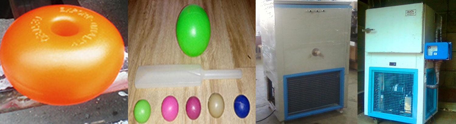
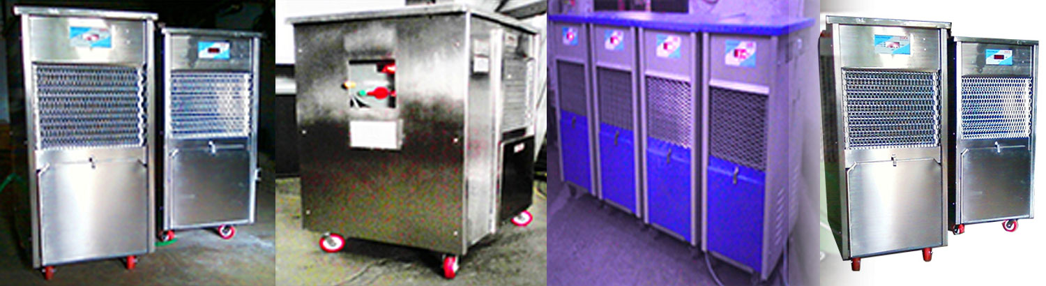
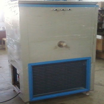
Central chiller systems often utilize large pump and tank stations.
First, the weight of the oil needs to be calculated as follows. Next, After the chiller is sized, add a 10% heat loss factor to arrive at approximately 14.8 tons of chiller. Cooling tonnage also equates to flow across the process. The following formula will provide an estimate for the quantity of water that must be supplied to the process.
Tons = gal/min x gT
Spectication
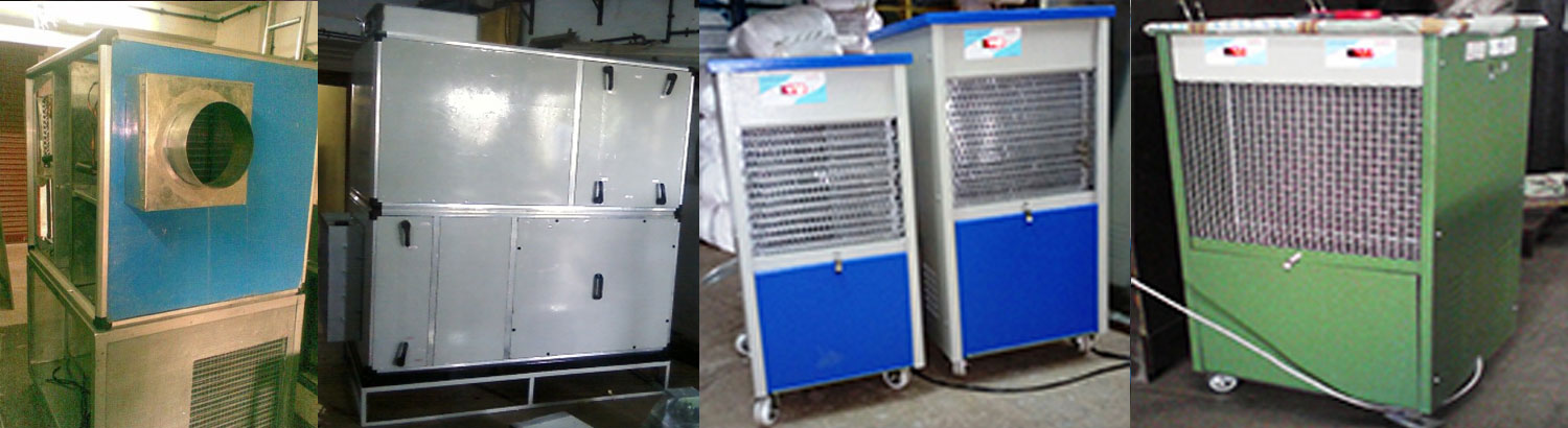
Hermetically sealed scroll / rotary compressor. Brazed plate Heat Exchanger / Chiller made out of stainless steel. Air cooled fin and tube type condenser coil having inner grooved copper tubes and hydrophobic coated slit aluminum fins. Chilled water inlet & outlet connections. Condenser fans having 4 Blades fan made out of aluminum. Centrifugal monoblock chiller water pump. High Pressure switch, Low pressure switch, flow switch. Electrical safety such as IP 54, Isolator switch, crank case heater, overload for pump; circuit breaker, motor protection, overload relay, built-in time delay for ON/OFF protection for compressor and fuses for control and crankcase heater. Controller having salient functions including control of inlet and outlet water temperature, auto loading / unloading of compressor, built-in time delays for compressor & chiller pump, single / reverse phase protection, in-built antifreeze safety. Polyester powder painted GI sheet casing in which compressor, condenser chiller & hydronic systems are mounted. All panels shall have bolted / locked joints for easy removal & serviceability. Inbuilt Electric Control panel. circuit safety devices including suction filter & flow switch
| Models (as per Ltr capacity) | Models (as per TR capacity) | |
| 1 | CH 20 | 0.5 TR |
| 2 | CH 50 | 0.5 TR |
| 3 | CH 100 | 1 TR |
| 4 | CH 200 | 2 TR |
| 5 | CH 250 | 3/4 TR |
| 6 | CH 300 | 5 TR |
| 7 | CH 500 | 7.5 TR |
| 8 | CH 750 | 10 TR |
| 9 | CH 1000 | 15 TR |
| 10 | CH 2000 | 30 TR |