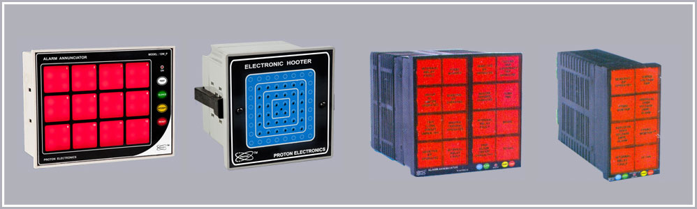
Fire Panel :
 A fire alarm control panel is an electronic panel that is the controlling component of a fire alarm system. The panel receives information from environmental sensors designed to detect changes associated with fire, monitors their operational integrate and provides for automatic control of equipment. The panel gives electrical energy to operate any associated sensor, control and relay. Fire detection is done using fire sensor. The micro controller based panel shows room temperature on seven segment display, sense fire faults of zones and controlling the alarm relay outputs
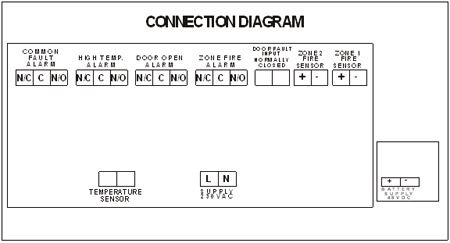
Connection Diagram
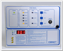
Working :
In normal working condition system is silent. Only ‘HEALTHY’ indication is flashing. Fire panel needs both 230 V AC and 48 V DC power input . If any one of them is absent AC/DC Power fault is appears. Room temperature is display on seven segment display. User has 3 keys FUN, Up arrow( ), Down Arrow( ) to change the room high as well as room temperature offset. To adjust the room temperature press FUN key 5 times continuously then using UP arrow & down Arrow Room temperature is adjusted.
Fire detection is done using smoke sensor. The smoke detector comes with blinking LED to indicated status of sensor. Once the fire condition is removed the LED and buzzer are reset. The Fire panel has 4 modes of operation:
| &POWER |
During power ON condition ‘HEALTHY’ green LED indication is continuously flashing. |
| FAULT : |
There are 5 LEDs on front panel to show the fault relay status. |
|
COMMON:
The Amber LED is flashing during any faults appears in the system. At the same time corresponding fault relay is ON
ZONE 1:
If Fire detection is done using smoke sensor of Zone 1 , the corresponding amber LED is flashing. At the same time corresponding fault relay is ON
ZONE 2:
If Fire detection is done using smoke sensor of Zone 2 , the amber LED is flashing. At the same time corresponding fault relay is ON
DOOR OPEN:
If door open fault detection is done using door open switch, the corresponding amber LED is flashing. At the same time corresponding fault relay is ON
AC/ DC POWER:
Any one of power input is fail detection is done, the corresponding amber LED is flashing. At the same time corresponding fault relay is ON |
| FIRE |
There are another 3 Red LEDS for COMMON, ZONE 1, ZONE 2 |
|
COMMON:
The Red LED is flashing during ZONE 1 or ZONE 2 faults appear in the system.
ZONE 1:
If Fire detection is done using smoke sensor of Zone 1 , the corresponding RED LED is flashing.
ZONE 2:
If Fire detection is done using smoke sensor of Zone 2 , the Red LED is flashing. |
| CONTROLS : |
There are 3 control keys and one isolate control switch |
|
ISOLATE CONTROLS:
On front panel there is 3 way key operated switch having green, yellow and red mark on the same. If key position is on Yellow mark the MUTE SOUNDER, TEST & RESET keys control are enable. If key position is on Green & Red mark the MUTE SOUNDER, TEST & RESET keys control are Disable
MUTE SOUNDER:
Normally whenever fault appears the corresponding LED is flashing and Sounder is ON. By using MUTE SOUNDER key SOUNTER is SILENCE for one minute. Assume ISOLATE switch is on Yellow mark.
TEST:
To check the LED, Relay & Sounder output, Hold TEST key for some time. When TEST key is release the LEDs are OFF and after one minute Relays are OFF
RESET:
All faults Relay are OFF while pressing RESET key |