


Our Products
- Safety Interlocks
- Liquid Rotor Resistance Starters (LRS)
- Liquid Rotor Resistance Regulator (LRR)
- Vapromatic Liquid Resistance starter
- Grid Rotor Resistance Speed Regulator (GRR)
- Buffer Resistance Panel
- Electric Control panel
- Control and Relay Panels
- Auto Transformer Starter (ATS)
- Neutral Grounding Resistors (NGR)

Contact Us
Enterprising Engineers
Mr. K.G. Bansal ( Managing Director )Mr. Nitin Bansal ( C.E.O.)
Mrs. Aparna Bansal ( Managing Partner )
(An ISO 9001:2008 Certified Company)
Plot No. 46 & 47, Sector-A,
Industrial Area, Govindpura,
Bhopal (MP)-462 023 (India)
Telefax : +91 755 2602964 / 2586684,
Office Mobile : +91 930 3196 591
E-mail : salesenquiry.ee@gmail.com ,
Website : www.enterprisingengineers.com
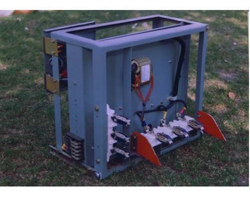
Vapromatic Liquid Resistance starter
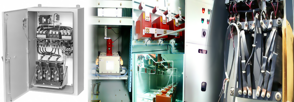
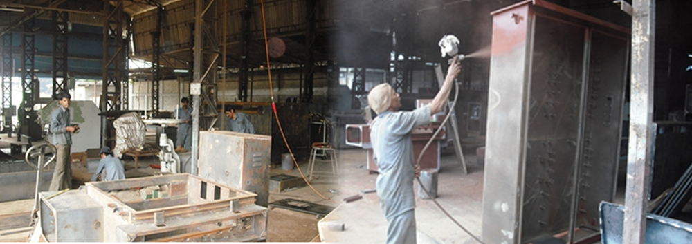
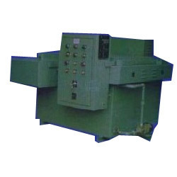 We are one of the most trusted names in electrical industry for designing & manufacturing of Vapromatic Type Liquid Rotor Resistance Starter.Construction of Vapromatic Type Liquid Rotor Resistance Starter :- The LRS (V) is a rectangular tank having electrolyte in it and works on the principle of resistance cutting based on different resistivity of electrolyte at different temperatures. The tank will be constructed from heavy gauge sheet steel and have enclosure protection of IP-42. The electrodes will be of zinc passivated M.S. suitably supported with insulator and bushings to sustain stress at the time of external faults. The fixed electrodes are mounted at the bottom of the tank and adjustable electrodes will be mounted at the top of the electrolyte tank through insulating bushing. The inside surface of the electrolyte tank will be painted with anticorrosive epoxy paint. Polypropylene phase barriers will be provided to prevent circulating current between the electrodes. Also the metallic resistance used for bringing the motor from 80% speed to rated speed would be mounted in a separate chamber which would be able to dissipate the generated heat. The tank will have accessories e.g. drain valve with brass plug at the bottom, separate plug for filling of electrolyte etc. Painting will be done by Hand Spray Gun M/cs with approved paint shade.
Main supply will be of 415 Volts and control supply for LRS (V) will be 230 or 110Volts and accordingly contactor coils would be of 230 or 110Volts only. Initial position and full speed position indicating contactors each having 2NO and 2NC potential free contacts will be provided for sequence interlocking. Electrolyte level and temperature sensor with alarm and trip contacts will be provided for sequence interlocking.
The LRS (V) will be complete with ample sized cable box and will be suitable for termination of PVC/XLPE Aluminum conductor cable. The terminal box will have detachable gland plate.
Control Panel having Switch-gear Components as :
(a) Temperature and Level Sensors.
(b) Initial and Final position contactors with multiply contacts.
(c) Two nos. of Electronic Timers of Reputed make, one for adjusting the time for Motor to reach up to 80% speed and other one is used if final shorting contactor is not operated after predetermined interval.
(d) Adequate rating and quantity of Step & Final Power contactor of Reputed make for smooth cutting of resistance and for final short-circuiting.
(e) Control Transformer (415V/230 or 110V) with control fuses (if required). Indicating Lamps (LED type) and TBs.
Interlocking for LRS (V) :
1. Motor would be ready for starting in RFS (Control Supply Healthy, Temp. within Limits).
2. Zero Position (RFS, both shorting contactors in un-operated position)
3. Final Position (If motor shorting not done in predetermined interval)
The Potential Free Contacts are required for Interlocks with:
01. HT/LT Panel : HT/LT to Trip & Start Signal
02. DCS : LRS (V) Healthy, Resistance IN/OUT, Liquid Level Low, Liquid Temp. High.
Indications (with LED type Lamps :
(a) Ready to Start
(b) Zero Position
(c) LRS (V) in Service
(d) Liquid Level Low
(e) Liquid Temperature High.
Terminal Blocks : All LRS (V) units will be provided with separate Terminal Blocks for termination of wires for External Connections.
Inspection and Testing : All routine tests and temperature rise tests as per relevant British Standards & IS.
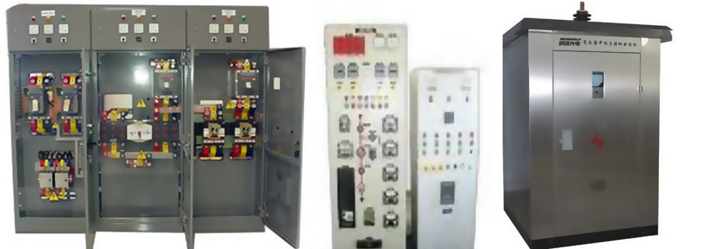
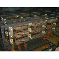
Grid Rotor Resistance Speed Regulator
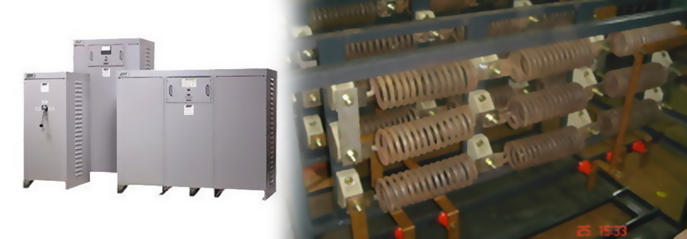
 We are one of the most trusted names in electrical industry for designing & manufacturing of Grid Rotor Resistance Speed Regulator.
It will have two units, free standing, floor mounting type made out of heavy gauge MS Sheet & painted with Primer & 2 coats of anti-corrosive paint.
We are one of the most trusted names in electrical industry for designing & manufacturing of Grid Rotor Resistance Speed Regulator.
It will have two units, free standing, floor mounting type made out of heavy gauge MS Sheet & painted with Primer & 2 coats of anti-corrosive paint.
One Unit :
It will have two Compartments i.e. Contactor Panel & Resistance Box. The Contactor Panel will be dust & Vermin proof & will house required Power Contactors to switch ON & OFF the Resistance Banks to attain required speed. The Resistance Box will be well Ventilated type & will house Resistance Banks. The Grid Resistance units will be made of SS Punched plates with high thermal capacity and temperature-rise up to 300°C over an ambient of 50°C. The Resistance unit will be assembled in Banks with good porcelain & other insulated material. The construction & mounting of Resistance Banks will be easy to maintain & replace. The Resistance Box & Contactor Panel will be mounted back to back in one unit. The connection between the Resistance Box and Contactor Panel as well as between Resistance Banks & Power Contactors are done by copper flats of sufficient cross-section. It will be provided suitable rating Air Break Power Contactor (AC 3 duty) of Reputed make (in delta connected) to suit the RA of motor. It will be suitable for controlling speed from 60% to 100% as 1.25% speed variation per step in total 32steps.
Second Unit :
It will be Control Panel/Speed Selector Panel free standing, Floor mounting, dust & vermin proof. It will house the necessary control units like Aux. Contactors, Timers, Overload Relays, Indicating Lamps, Push Buttons etc. The Mini PLC used for setting of Logic controls of different speeds.
Construction :
Sheet Steel Clad, free standing, floor mounting type made out of 2mm. thick sheet with suitable angle iron reinforcement. The paint finish will be Light Grey 631 of IS:5. The Grid Resistance Regulator Panel basically comprises of 2 portions, the Resistor unit and the Contactor Panel. The Resistor unit is attached to the back of Contactor Panel and comprises Grid Elements assembled in the form of banks, stacked one above the other. All the Grids will be housed in this panel. The top will be covered with weld mesh only. Hot Air outlet ducting if required, has to be arranged at top by you. The Power Contactor Panel houses the Rotor Contactors suitably interconnected with adequately rated copper jumpers. A Bus Bar arrangement to connect 4-6Nos. Rotor Cables will be provided at bottom of panel with a suitable clearance from gland plate. The inter connection between Resistor Cubicle and Contactor Cubicle will be done through epoxy insulated wall mounted bushing sealed with gaskets. Proper heat shield arrangement will be made to see that heat transfer does not take place from Resistor Cubicle to Contactor Cubicle. The make of Switch gear components will be of reputed make like C&S, L&T, GE, BCH, ABB, Siemens, TC etc.
Cooling Blowers :
Cooling Blowers are of either Axial or centrifugal type. The MS Impellers are balanced on a dynamic balancing machine to avoid vibrations. The air output will be as per the requirement of each equipment. While erection, the foundation has to laid separately for blowers and the foundation from blower to panel has to be made through canvas bellows. It is prevent the vibrations of blowers getting transferred to GR Panel.
Tests to be conducted :
1. Sequence/Operational-Functional Test as per Schematic/Wiring drawing.
2. Megger Test between Phase to Phase & Phase to Ground by 500 V megger.
3. High Voltage withstand test of 2.5KV for 1 minute on Control Circuit.
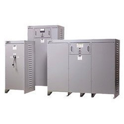
Buffer Resistance Panel
 We are one of the most trusted names in electrical industry for designing & manufacturing of Buffer Resistance Panel. Buffer Resistance panel will be made-out by 2mm thick CRCA MS sheet steel, free standing, floor mounting, dust & vermin proof construction, indoor type, external & internal surfaces cleaned by chemical treatment, duly painted with approved paint shade. The Buffer Resistance panel having a set of Punched SS grid resistance cont. rated for the RA of the motor with a max. temp rise of 375 to 400oC and having an adequate ohmic value/ phase to run the slip ring motor at 15% slip regulation/regulator.
Electric Control panel
Enterprising Engineers is a versatile manufacturer and exporter of a unique range of sophisticated Electric Control Panel. We have used the finest quality of raw material to manufacture these highly advanced devices that are widely used in several industries.
Our extensive range of Electric Control Panel includes highly advanced devices such as Drawout / Fixed Motor Control Centres, Installation & Commissioning Electrical Plants, Earthing Accessories, Auto-Transformer Starters Panel, Power Control Centres & Distribution Boards and Liquid Resistance Starter.
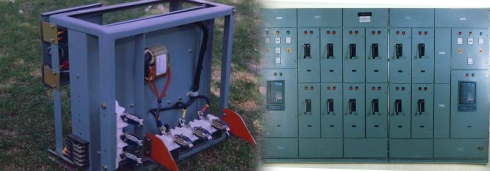
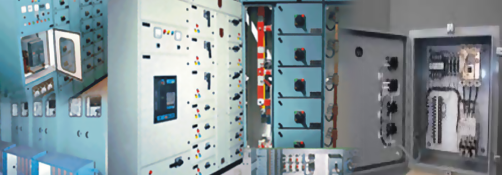
Motor Control Centres(MCC) - Drawout and Fixed
 This extensive range of Electric Control Panel has been manufactured for Controlling Electric Motors & other Equipments from a Central Location. Our expert team of engineers has designed these devices to handle Switching, Protection, Isolating, Distribution & Control Functions. This range of high-tech Electric Control Panel has been implanted with self aligning power & control terminals. These devices are immensely used in Power Plants, Cement, Paper, Steel, Fertilizer, Petrochemical & other industries.
Features:
1. Drawout modules provided with self aligning Power & Control terminals
2. Contacts Silver Plated & Spring loaded to ensure adequate contact pressure to ensure long life. Service, Test & Isolated positions are clearly indicated.
3. Gravity operated safety shutter operates automatically when module is withdrawn for added safety.
4. Swing out instrument panel enabling the operator to read out and reset the relays.
5. Cable Alleys with ample space segregated from Feeder Sections for power & control cables.
6. Single or Double front for specific requirement.
7. Exceptionally large MCCs are built in convenient sections with lifting hooks on top.
Power Control Centres & Distribution Boards
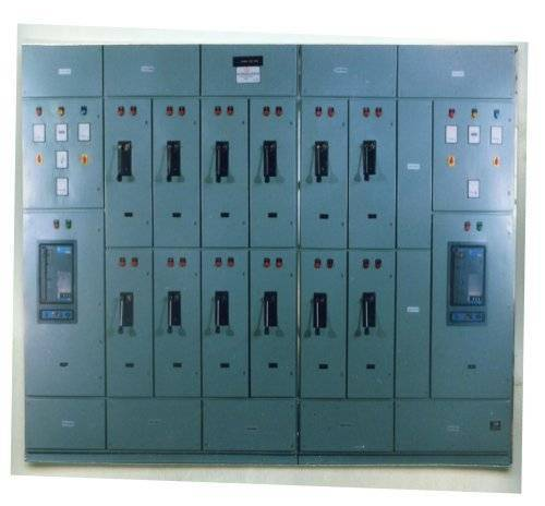 Our Power Control Centres & Distribution Boards are appreciated globally for their extreme performance and reliability. Our expertise have designed them with separate compartments for Control, Relay & Metering apparatuses with full width cabling chamber at back and ACBs in fixed or draw-out execution.
Applications
The Power Control Centres & Distribution Boards manufactured by us are widely used for the several applications in various industries:
1. For L.T. Switchgears to Control and Distribute power.
2. Power Stations
3. Large Industrial Plants & Process Industries etc.
Features
1. Horizontal and Vertical bus bars supported on DMC/SMC Insulators are housed in totally enclosed compartments to prevent dust & vermin.
2. Electrolytic grade Aluminum alloy bus bars are provided with heat shrinkable PVC colored sleeves.
3. Single or Double front for specific requirement.
4. Exceptionally large PCCs are built in convenient sections with lifting hooks on top.

