 Iron caste heavy base
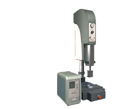
Information
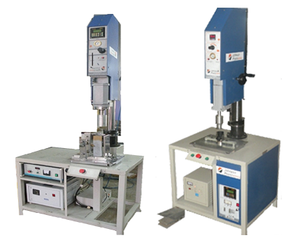
⇓ Construction Of Ultrasonic Machine
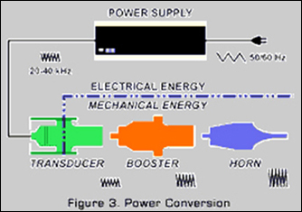 Ultrasonic energy is mechanical vibratory energy which operates at frequencies beyond audible sound, or 18,000 Hz (18,000 Hz being the upper threshold of the normal human hearing range). Two basic frequencies are used; 20,000 Hz and 40,000 Hz, depending on the application. Selection is based upon the required power levels, the amplitude of vibration required and the size of the ultrasonic tool to be used. Frequency is important because it directly effects the power available and the tool size. It is easier to generate and control high power levels at the lower frequency. Also, ultrasonic tools are resonant members whose size is inversely proportional to their operating frequency. The generation of ultrasonic energy starts with conversion of conventional 50 or 60 Hz electrical power to 20,000 or 40,000 Hz electrical energy by a solid state power supply.
⇓ Joint Design For Ultrasonic Plastic Welding
Correct joint design is important for successful ultrasonic welding.
Sometimes while developing a new part for ultrasonic welding, the equipment is working okay, the horn & fixture also well designed but if joint design for welding is not correct, it will create problem.
The joint design must be considered in design stage of the product.
If we are not giving any consideration for joint design, then
 Patchy welding may occur.
- Hermetic or leak proof sealing is not possible.
- More Power will be required for welding.
In ultrasonic welding, there are two basic joint types
- Energy director joint
- Shear joint
ENERGY DIRECTOR joint is preferable in amorphous structure material, sometimes in Semi-Crystalline materials also this joint is given.
Joint Design For Ultrasonic Plastic Welding
The molten material builds at the contact area of the energy director between the parts to be welded. The ultrasonic waves are transferred through the part to the energy director. Common standard energy directors include.
Basic 90 degrees energy director Energy director step joint
⇓ Energy director with tongue & groove joint
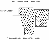 The joint consists of a small triangular section molded into the component and typically running the length of joint perimeter. The purpose of energy director is to focus the ultrasonic energy at the apex, resulting in Rapid built up of heat. This causes the triangular section to melt and flow across joint interfaces, forming a weld.
The type of thermoplastic to be welded determines the form of the triangular energy director. Amorphous material require a right – angled triangle with the 90 degrees angle at apex. For semi crystalline materials a 60 degrees equilateral projection is used. Typical heights for energy directors are between 0.2 to 1.0 mm depending on the material.
Energy director with tongue & groove joint
Generally if we consider the wall thickness of part that is the thickness of wall on which energy director is to be formed as basis, then Height of energy director will be 1/8 of the wall thickness. The base width will be 1/4th of the wall thickness.
When the wall thickness enough to produce an energy director than maximum size, more than 01 energy directors can be given.
In semi crystalline larger & sharper energy director is used Energy director with step joint.
This meets all three requirements.
- A uniform contact area
- A small initial contact area
- A means of self alignment.
It’s strength is relatively less than a butt joints only a part of the wall in a step joint is welded. But it hides all flash inside. The material from the energy director will typically flow into the clearance gap between the steps.
A step joint needs a minimum wall thickness of 2mm. The height & width of the step are each 1/3 of the total wall thickness T= W/3. The step height should be marginally greater than the depth i.e. 0.1mm, this adds aesthetic s to the welded assembly and hides parallelism imperfections in the molded parts.
⇓ Tongue & groove joint
It meets all three requirements as in step joint. But apart from that , it eliminates internal & external flash. Where self location and the flash are important, this design is used. It ensures low pressure leak tight seals. Although the necessity to maintain clearance on both sides of the tongue makes it difficult to mould, interference between the parts must be strictly avoided. This clearance also provides space for molten plastic
It’s weld strength is relatively lower-only a third of wall thickness is typically welded. The minimum wall thickness recommended for tongue –and –groove design is 3mm. Dimension for energy director remain same. Both the height & width of tongue, are f1/3 the wall thickness.
The groove is 0.1 to 0.2mm wider than the tounge,and the depth of the groove is 0.1mm to 0.25mm less than the height of the tongue.
As with the step joint, the slight gap designed into the welded assembly provides for better aesthetics.
Recent experiment shows that if the energy director mates with a roughened surface ,s opposed to a normal smooth surface ,the welding is quicker, and a better weld is achieved.
⇓ The shear joint
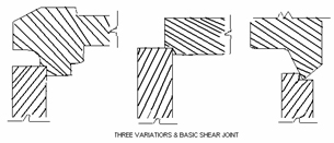
The shear joint is used when a strong, leak tight seal is desired especially with Semi-crystalline polymers .
The shear joint
A positive interference between the mating parts is a shear joint. The interference can only be melted away with ultrasonic energy. A shear joint meets all three basic requirements of good joint design. A locating recess help self alignment of the parts, and the line contact provides uniform contact area, small initial contact area. On application of ultrasonic energy and pressure, the contact surfaces rub together, generate heat & begin to melt and enlarge, till the designed depth of weld is achieved. As the contact surfaces melt, welding is achieved. The continuous smearing action of mating surfaces at the welding interface fills all voids; it also limits exposure to air, consequent premature solidification and degradation. This action produces a leak tight weld and strong structural strength. A fixture plays an important role in shear joint welding, and great care needs to be taken in designing it correctly. It should prevent a snap fit due to flexing of the walls during welding. The fixture should rigidly support the walls of the fixture part up to the joint interface. Sometimes a spilt design or an ejector is necessary to eject the tightly squeezed in welded assembly from the fixture.
Recommended values of the interference required in the shear joint are dependant on the size of part.
| Maximum dia | Interference preside | Dimensional tolerance | Locating recess | Depth of weld. |
| < 18mm | 0.2 to0.3mm | +/- 0.025mm | 0.5 to 0.8mm | 1.25to 1.5 * wall thickness |
| 18 to 35mm | 0.3 to 0.4mm | +/- 0.050mm | .5 to 0.8mm | As above |
| >35mm | 0.4-0.5mm | +/- 0.075mm | .5 to 0.8mm | As above |
Minimum wall thickness 2.0 mm.
Types Of Shear Joint
SOME OTHER CONSIDERATIONS
Several aspects need to be considered in deciding which part should make contact with the horn, and which part should be held stationary in the fixture.
Ease of assembly, handling the individual components and part geometry are factors to be considered .
From the ultrasonic point of view, however the material to be welded is important. Losses in transmission of ultrasonic energy through amorphous resins are low and losses through semi-crystalline material are higher.
This is because the orderly molecular structure of semi crystalline resins absorbs ultrasonics.Whereas the random molecular arrangement of amorphous resins transmits ultrasonic well.
⇓ Ultrasonic plastic compatibility chart
he term plastic can be used for thermoplastic or thermo set materials. Most thermo set material can not be ultrasonically bonded as they burn when heated. Thermoplastics are normal categorized as amorphous or crystalline.
Amorphous material exhibits a random, spaghetti like structure. They are good at transmitting the ultrasonic energy to the part that needs to be bonded. Amorphous material include: ABS, Polycarbonate and Acrylic. Crystalline materials have an ordered pattern, and have a well defined melting temperature.
Crystalline materials include: Acetal, Nylon, Polyester, Polyethylene and polypropylene.
The following grid can be used to assist with plastics suitable for ultrasonic welding.
E=Excellent, G=Good, F=Fair, P=Poor, NO=Not suitable for ultrasonic welding.
| THERMOPLASTIC | SPOT WELDING | STAKING | INSERTING | NEAR FIELD WELDING | FAR FIELD WELDING |
| ABS | E | E | E | E | G |
| ABS/polycarbonate | G | G | G | G | F |
| ABS/PVC | G | G | F | G | F |
| Acrylic | G | F | G | G | F |
| Acrylic multi-polymer-xt polymer | G | G | G | G | F |
| Acrylic/PVC | G | G | F | G | F |
| Acrylic-impact modified | F | F | P | F | P |
| AMORPHOUS POLYMERS | SPOT WELDING | STAKING | INSERTING | NEAR FIELD WELDING | FAR FIELD WELDING |
| Butadiene-styrene(bds) | G | G | G | G | F |
| Cellulosics-ca,cab,cap | P | G | E | P | NO |
| Modified phenylene oxide | E | E | E | E | G |
| Polyarylate | F | F | G | G | F |
| Polycarbonate | G | F | G | G | F |
| Polyetherimide | G | G | E | E | G |
| Polystyrene, g.p. | F | F | G | E | E |
| Polystyrene, impact modified | F | F | G | G | P |
| PVC-rigid | F | G | F | P | P |
| PVC-flexible | P | NO | NO | P | NO |
| San-nas-asa | F | F | G | E | E |
| Styrene-maleic-anhydride | E | E | E | E | G |
| Sulfone polymers | F | F | G | G | F |
| CRYSTALLINE POLYMERS | |||||
| Acetal copolymers | F | F | G | G | F |
| Acetal homopolymer | F | F | G | G | F |
| Fluoropolymer | NO | NO | NO | P | NO |
| Nylon | F | F | G | G | F |
| PC-pet | G | G | E | E | G |
| Polyester-pbt | F | F | G | G | F |
| Polyester-pet | F | F | G | G | F |
| Polyetheretherketone | G | G | E | E | G |
| Polyethylene (ldpe,hdpe) | G | F | G | P | P |
| Polyarylate | Polyethylene (uhmw) | NO | NO | NO | NO |
| Polymethylpentene | G | F | E | F | P |
| Polyphenylene sulfide | F | P | G | G | F |
| Polypropylene | E | E | G | F-P | P |
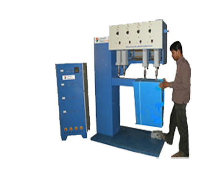
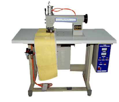
⇓ Operation of Plastic Welding Machine
The success of joining parts using a Plastic Welding Machine depends upon many factors including joint design, dimensions and composition of the work piece. Once an appropriate joint has been designed and a horn built for the particular application the right combination of setting of weld time, hold time, amplitude and pressure must be determined. These parameters vary from application to application.
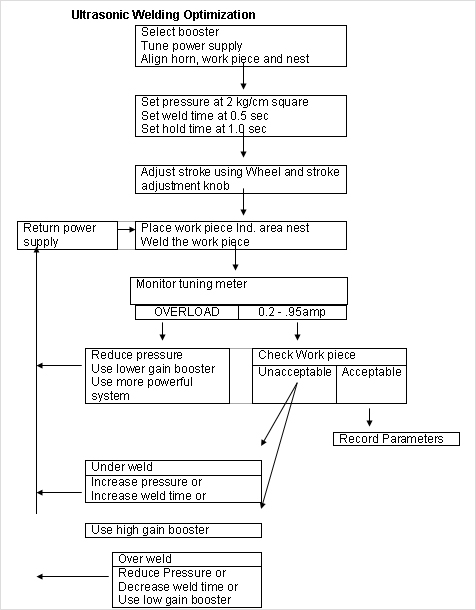
Unlikely that optimum results will be obtained on the first try. Each variable should be studied independently by welding several groups of parts at a number of settings. While the other two variables are held constant. The results of each weld should be observed and the optimum setting for that variable recorded. Only one variable should be changed at a time. As a rule of thumb the inter-relationship between the other variable is as follows :
| When | Then |
| Amplitude is increased Pressure is increased. Weld time is increased |
Pressure and weld time should be decreased Amplitude and weld time should be decreased Amplitude and weld time should be decreased |
Weld Time
The correct weld time for each application is determined by trial and error. That is important to avoid over welding. In addition to creating excessive flash which may require trimming, the horn may mark on the surface of the work piece, and cause melting and fracturing of portions of the parts away from the joint area, especially with holes, weld lines and sharp corners in molded parts.
Hold Time
Hold time is not a critical variable. One second is usually sufficient for most application unless an internal load tends to disassemble welded parts, such as a coil spring compressed prior to welding.
Amplitude
The first step in optimizing conditions is to select a horn/ booster combination, which will give the required amplitude. For parts one inch (25.5 mm) in diameter or greater, select initially a high amplitude booster such as a 1:1.5 booster. For smaller parts, start with a 1:1 booster. Determine optimum amplitude. If there appears to be little or no difference, use the booster giving the highest amplitude.
Seven standard boosters, color coded for ease of identification, are available
| Color | Gain ratio | Amplitude |
| Black Silver Gold |
1:2.5 1:2 1:1.5 |
Increase Amplitude |
| Green Purple |
1:1 1:0.6 |
No change |
| Blue Red |
1:0.5 1:0.4 |
Decrease Amplitude |
Pressure
Sufficient pressure should be applied to the part so that the mating surfaces contact each other. If the pressure is too low, the equipment will run inefficiently causing unnecessarily long weld time cycles, marking of the parts of poor welding. If the pressure is too high, the horn will stop vibrating the part might fracture through power supply might overload.
Welding
The parts to be assembled are held together under pressure and ultrasonic vibrations force the parts to rub against each other at high frequency. The result is highly localized frictional heating at the joint line or common interface. The material in the immediate vicinity melts, usually in less than one second, and flows throughout the applied pressure. When the Ultrasonic vibration stops, the molten plastic solidifies and a high strength bond results
Trouble Shooting
Welding Trouble shooting Guide
| Problem | Solution |
| Under weld | Increases weld time. Increase amplitude (Change booster) Increase down speed |
| Overload | Reduce weld time Reduce pressure Reduce amplitude (Change booster) |
| Insufficient strength | Increase weld time Increase hold time Increase amplitude (Change booster) Decrease down speed |
| Excessive flash | Decrease weld time Decrease amplitude ( Change booster) Decrease pressure Decrease size of energy director. Loosen part tolerance |
| Surface marking | Decrease amplitude Decrease weld time Decrease pressure Check for loose studs Check coupling between horn and booster Check for cracked horn Check fit of horn to part Check fit of part to fixture Check for proper fixturing Chrome – plate horn and /or fixture Shim fixture as required |
| Part fractures | Decrease pressure Decrease weld time Decrease down speed |
| Part Cracks or separates after Pressure is released |
Increase hold time Increase weld time Increase amplitude Increase pressure |
| Material degrades (Flaking-bubbling) |
Decrease weld time Decrease amplitude Decrease pressure |